Gas Welding Systems
GENERAL INFORMATION
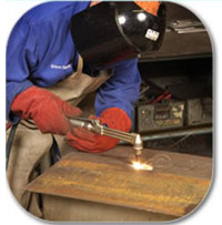
Gas torch welding was perfected in the early 1900's and is a Handy skill that can be learned with some knowledge and practice. Today, it is still a very versatile system with many applications. There are two basic types of gas torches: Air-Fuel and Oxy-Fuel. Three adjustments that are used on a torch: fuel flow, oxygen flow -and tip size. Firetec Marine has prepare all the standard manipulation brochure to your working stuff at time, every parts in use are changeable by your need.
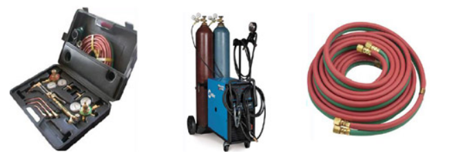
Apparatus
The apparatus used in gas welding consists basically of an oxygen source and Acetylene source (usually cylinders), two pressure regulators and two flexible hoses (one of each for each cylinder), and a torch. This sort of torch can also be used for soldering and brazing. The cylinders are often carried in a special wheeled trolley.
Regulator
The regulator is used to control pressure from the tanks by reducing pressure and regulating flow rate. Oxy-gas regulators usually have two stages: The first stage of the regulator releases the gas at a constant rate from the cylinder despite the pressure in the cylinder becoming less as the gas in the cylinder is used. The second stage of the regulator controls the pressure reduction from the intermediate pressure to low pressure. It is constant flow. The valve assembly has two pressure gauges, one indicating cylinder pressure, the other indicating hose pressure. Some oxy-gas regulators only have one stage, and one pressure gauge, and in them the gas flow habecomes less as the cylinder pressure drops.
Gas hoses
The hoses used are specifically designed for welding and cutting.The hose is usually a double-hose design, meaning that there are two hoses joined together. The oxygen hose is green and the fuel hose is red. The type of gas the hose will be carrying is important because the connections will have different threads for different types of gas. Acetylene (red) will use left hand threads and a groove cut into the nut, while the oxygen (green) will use right-hand threads. This is a safety precaution to prevent hoses from being hooked up the wrong way. There are basically two types of connections that can be used. The first is using a jubilee clip. The second option is using a crimped connector. The second option is probably safer as it is harder for this type of connection to come loose. The hoses should also be clipped together at intervals approximately 3 feet apart.
Non-return valve
Between the regulator and hose, and ideally between hose and torch on both oxygen and fuel lines, a flashback arrestor and/or non-return valve should be installed to prevent flame or oxygen-fuel mixture being
pushed back into either cylinder and damaging the equipment or making a cylinder explode. The flashback arrestor (not to be confused with a check valve) prevents the shock waves from downstream coming back up the hoses and entering the cylinder (possibly rupturing it), as there are quantities of fuel/oxygen mixtures inside parts of the equipment (specifically within the mixer and blowpipe/nozzle) that may explode if the equipment is incorrectly shut down; and acetylene decomposes at excessive pressures or temperatures. The flashback arrestor will re -main switched off until someone resets it, in case the pressure wave created a leak downstream of the arrestor.
Torches
The torch is the part that the welder holds and manipulates to make the weld. It has a connection and valve for the fuel gas and a connection and valve for the oxygen, a handle for the welder to grasp, a mixing chamber (set at an angle) where the fuel gas and oxygen mix, with a tip where the flame forms.
Welding torch
A welding torch head is used to weld metals. It can be identified by habecomes ving only one or two pipes running to the nozzle and no oxygen-blast trigger and two valve knobs at the bottom of the handle letting the operator adjust the oxygen flow and fuel flow.
Cutting torch
A cutting torch head is used to cut metal. It is similar to a welding torch, but can be identified by having three pipes that go to a 90 degree nozzle and by the oxygen-blast trigger. Only iron and steel can be cut using this method. The metal is first heated by the flame until it is cherry red. Once this temperature is attained, oxygen is supplied to the heated parts by pressing the "oxygen-blast trigger". This oxygen reacts with the metal, forming iron oxide and producing heat. It is this heat which continues the cutting process. The cutting torch only heats the metal to start the process; further heat is provided by the burning metal
Acetylene
Acetylene is the primary fuel for oxy-fuel welding and is the fuel of choice for repair work and general cutting and welding. Acetylene gas is shipped in special cylinders designed to keep the gas dissolved. The cylinders are packed with porous materials (e.g. kapok fibre, diatomaceous earth, or (formerly) asbestos), then filled to around 50% capacity with acetone, as acetylene is acetone soluble This method is necessary because above 207 kPa (30 lbf/in2) (absolute pressure) acetylene is unstable and may explode. This may happen in fire emergencies, where police snipers are sometimes called in by fire service to puncture the welding vessels with rifle shot to let the pressure escape. (Once the heat reaction starts, cooling the tanks with water spray cannot prevent the eventual explosion but only delay it, so the tank must be punctured to prevent much destruction).
Welding
The flame is applied to the base metal and held until a small puddle of molten metal is formed. The puddle is moved along the path where the weld bead is desired. Usually, more metal is added to the puddle as it is moved along by means of dipping metal from a welding rod or filler rod into the molten metal puddle. The metal puddle will travel to matwards where the metal is the hottest. This is accomplished through torch manipulation by the welder. The amount of heat applied to the metal is a function of the welding tip size, the speed of travel, and the welding position. The flame size is determined by the welding tip size.The proper tip size is determined by the metal thickness and the joint
design. Welding gas pressures using oxy-acetylene are set in accordancewith the manufacturer's recommendations. The welder will modifythe speed of welding travel to maintain a uniform bead width.Uniformity is a quality attribute indicating good workmanship. Trainedwelders are taught to keep the bead the same size at the beginning of
the weld as at the end. If the bead gets too wide, the welder increasesthe speed of welding travel. If the bead gets too narrow or if the weldpuddle is lost, the welder slows down the speed of travel. Weldingin the vertical or overhead positions is typically slower than welding inthe flat or horizontal positions. The welder must add the filler rod to the
molten puddle. The welder must also keep the filler metal in the hot outerflame zone when not adding it to the puddle to protect filler metal fromoxidation. Do not let the welding flame burn off the filler metal. The metalwill not wet into the base metal and will look like a series of cold dots onthe base metal. There is very little strength in a cold weld. When the fillermetal is properly added to the molten puddle, the resulting weld will bestronger than the original base metal.
Cutting
For cutting, the set-up is a little different. A cutting torch has a 60 or 90-degree angled head with orifices placed around a central jet. The outer jets are for preheat flames of oxygen and acetylene. The central jet carries only oxygen for cutting. The use of a number of preheating flames, rather than a single flame makes it possible to change the direction of the cut as desired without changing the position of the nozzle or the the cut as desired without changing the position of the nozzle or the giving a better preheat balance. Manufacturers have developed custom tips for Mapp, propane, and polypropylene gases to optimize the flames from these alternate fuel gases. The flame is not intended to melt the metal, but to bring it to its ignition temperature. The torch's trigger blows extra oxygen at higher pressures down the torch's third tube out of the central jet into the workpiece, causing the metal to burn and blowing the resulting molten oxide through to the other side. The ideal kerf is a narrow gap with a sharp edge on either side of the workpiece; overheating the workpiece and thus melting through it causes a rounded edge. Cutting is initiated by heating the edge or leading face (as in cutting sh apes such as round rod) of the steel to the ignition temperature (approximately bright cherry red heat) using the pre-heat jets only, then using the separate cutting oxygen valve to release the oxygen from the central jet. The oxygen chemically combines with the iron in the ferrous mat erial to instantly oxidize the iron into molten iron oxide, producing the cut. Initiating a cut in the middle of a workpiece is known as piercing.
All statements, information and data presented herein are believed to be accurate and reliable but are not to be taken as a guarantee, express warranty or implied warranty of merchantability or fitness fora particular purpose, or representation, express or implied, for which seller assumes legal responsibility , and they are offered solely for your consideration, investigation and verification. Statements or suggestions concerning possible use of this product are made without representation or warranty that any such use is free of patent infringement and are no recommendations to infringe on any patent.